
Ramin Nabati
Sunday, May 10, 2020
Radar Region Proposal Network
Introduction
Radar Region Proposal Network (RRPN) is a Radar-based real-time region proposal algorithm for object detection in autonomous driving vehicles. RRPN generates object proposals by mapping Radar detections to the image coordinate system and generating pre-defined anchor boxes for each mapped Radar detection point. These anchor boxes are then transformed and scaled based on the object’s distance from the vehicle, to provide more accurate proposals for the detected objects. The generated proposals can be used in any two-stage object detection network such as Fast-RCNN. Relying only on Radar detections to generate object proposals makes an extremely fast RPN, making it suitable for autonomous driving applications. Aside from being a RPN for an object detection algorithm, the proposed network also inherently acts as a sensor fusion algorithm by fusing the Radar and camera data to obtain higher accuracy and reliability.
RRPN also provides an attention mechanism to focus the underlying computational resources on the more important parts of the input data. While in other object detection applications the entire image may be of equal importance. In an autonomous driving application more attention needs to be given to objects on the road. For example in a highway driving scenario, the perception system needs to be able to detect all the vehicles on the road, but there is no need to dedicate resources to detect a picture of a vehicle on a billboard. A Radar based RPN focuses only on the physical objects surrounding the vehicle, hence inherently creating an attention mechanism focusing on parts of the input image that are more important.
Our Approach
The first step in generating ROIs is mapping the radar detections from the vehicle coordinates to the camera-view coordinates. Radar detections are reported in a bird’s eye view perspective as shown in image (a) in the figure below, with the object’s range and azimuth measured in the vehicle’s coordinate system. By mapping these detections to the camera-view coordinates, we are able to associate the objects detected by the Radars to those seen in the images obtained by the camera.
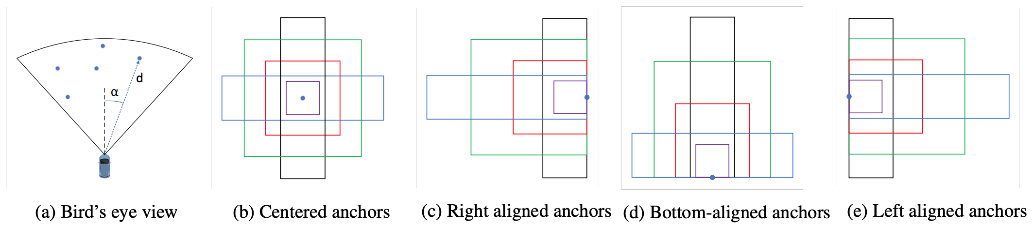
Generating anchors from radar detections.
Anchor Generation
Once the Radar detections are mapped to the image coordinates, we have the approximate location of every detected object in the image. These mapped Radar detections, hereafter called Points of Interest (POI), provide valuable information about the objects in each image, without any processing on the image itself. Having this information, a simple approach for proposing ROIs would be introducing a bounding box centered at every POI. One problem with this approach is that Radar detections are not always mapped to the center of the detected objects in every image. Another problem is the fact that Radars do not provide any information about the size of the detected objects and proposing a fixed-size bounding box for objects of different sizes would not be an effective approach.
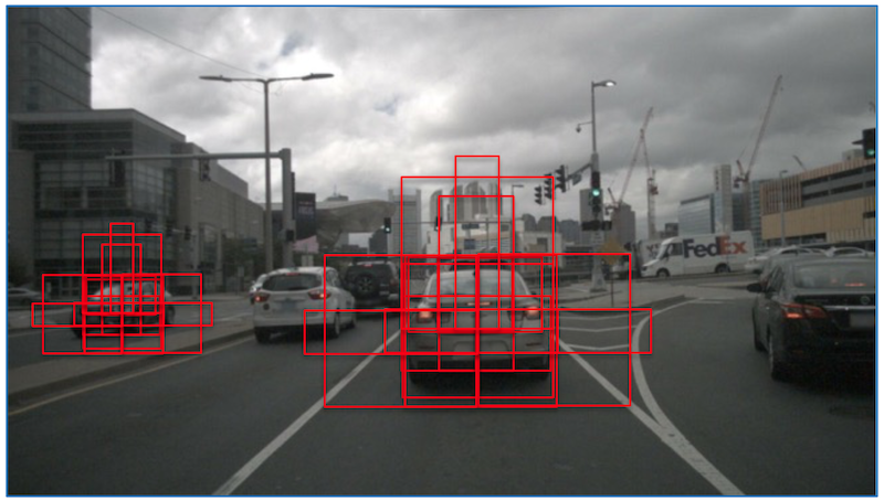
We use the idea of anchor bounding boxes from Faster R-CNN to alleviate the problems mentioned above. For every POI, we generate several bounding boxes with different sizes and aspect ratios centered at the POI, as shown in the figure above (b). We use 4 different sizes and 3 different aspect ratios to generate these anchors. To account for the fact that the POI is not always mapped to the center of the object in the image coordinate, we also generate different translated versions of the anchors. These translated anchors provide more accurate bounding boxes when the POI is mapped towards the right, left or the bottom of the object as shown in figure above. The generated anchors for a radar detection is shown in the figure below:

Anchors generated from a radar detection
Distance Compensation
The distance of each object from the vehicle plays an important role in determining its size in the image. Generally, objects’ sizes in an image have an inverse relationship with their distance from the camera. Radar detections have the range information for every detected object, which is used in this step to scale all generated anchors. We use the following formula to determine the scaling factor to use on the anchors:
$$ S_i = \alpha \dfrac{1}{d_i} + \beta $$
where $d_i$ is the distance to the $i$th object, and $\alpha$ and $\beta$ are two parameters used to adjust the scale factor. These parameters are learned by maximizing the Intersection Over Union (IOU) between the generated bounding boxes and the ground truth bounding boxes in each image. The generated proposals for two radar detection points after distance compensation are shown in the figure below:
Proposals after distance compensation.
Figures below show a sample image and the proposals generated from all radar detections:
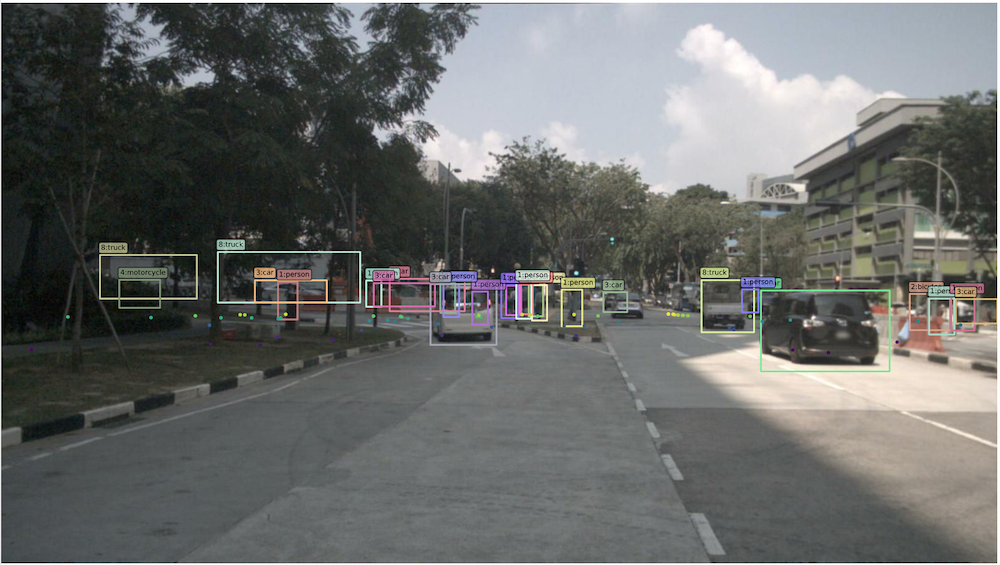
Sample image with ground truth and radar detections
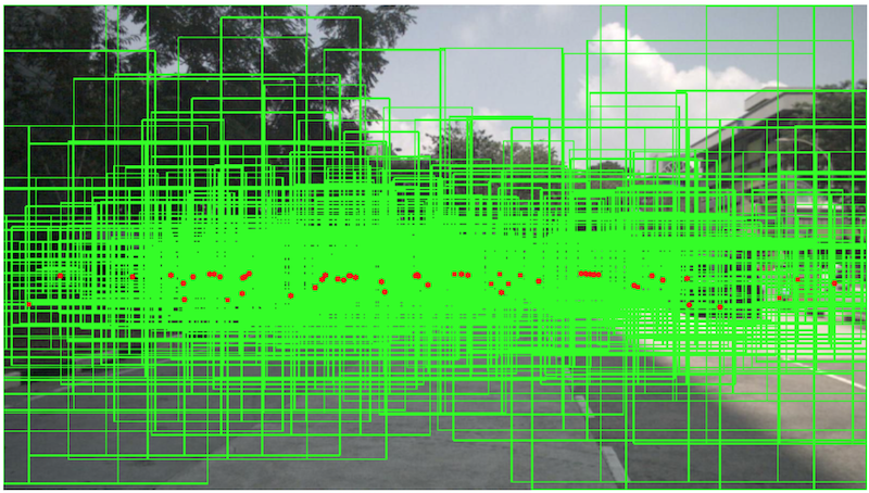
Generated proposals from all radar detections.
The evaluation results are provided in our ICIP 2019 conference paper.